
If you want to build your effectors from scratch, You may have a lot of questions and wants to know the tips of them.
We are pleased to announce to launch The ECB Effector Building Course for beginners.The instructor is Hiroshi Ozawa, Sound Project “SIVA”‘s founder. He is also JPBA’s initiator.
This web course would like to introduce not only “How to build it” but also Hiroshi’s recommended tools, parts, etc…
We are providing to the contents that useful for not only effector enthusiasts but also who want to be a professional effect builder.
▼Instructor
 | Hiroshi Ozawa. Sound Project “SIVA”’s founder, effect designer and builder. “Siva” is the japan’s most famous “ITA effector” brand. “ITA” means “painful” literally, but it is an “OTAKU” slang in Japan, not a negative meaning. Almost pedal cover designs are seeking to be functional or cool. However, Siva is going a different way. Siva believes good effector needs a good cover design.He says “If it’s a cute girl? Your motivation will be higher.” » Sound Project “SIVA” |
Part1 “Tools”
Part2 “Parts and components-1”
Part3 “Parts and components-2”
Part4 “Case (chassis) processing”
Part5 “Painting or coating and finishing”
Part6 “Building an electric circuit board”
Part7 “Assembly”
Part8 “Work example”
Part9 “PCB electric board processing(KiCAD)”
※Subject may change without notice.
I would like to start to “Chassis processing” lecture today. Also, This is a first part of the “Actual work process” lecture. I have ever heard it is a hardest things to “Chassis processing” in the building a effectors.
This time, I will show you wiring diagram in this lecture but it is just a materials of this lecture. I will teach you about how to design the wiring or making circuit board in next section.I would like to you will try and enjoy effector building for the time being.
Today, I will show you how to make 1 knob clean booster. This is a good at leaning effector building for bigginers and it has an essential of technical and design for effector building.
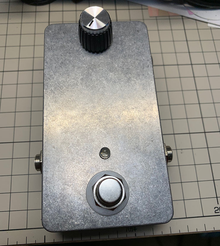
Well, Today, we will build such an effector. There is no finishing, but I will teach you them in other lectuer.
1:Design
Let’s design what kind of effector you want to build and parts location. Also, We will make a paper template of Chassis processing.
2:Making punch.
Use the paper template to determine the location of the holes in the chassis..
3:Drilling a hole
Drill holes of the required size at the position of the punched housing.
1:Design
First of all, Imagine your desired effector and write it down as a concrete thing.
Don’t think difficult. In the beginning, we do not draw wiring diagrams and circuit diagrams. You can do it if you can follow me step by step.
We will build a 1 knob booster in this time. This is a circuit diagram of this pedal.
One transistor inside, simple consist, but it provide mid boost, you can feel rich and fat tone. Good at lead play.
In this circuit diagram, the description around the switch is omitted. The configuration around the switch uses “True bypass method”, which requires a small number of parts. Wiring around the switch will be explained in the other lectuer of this series.
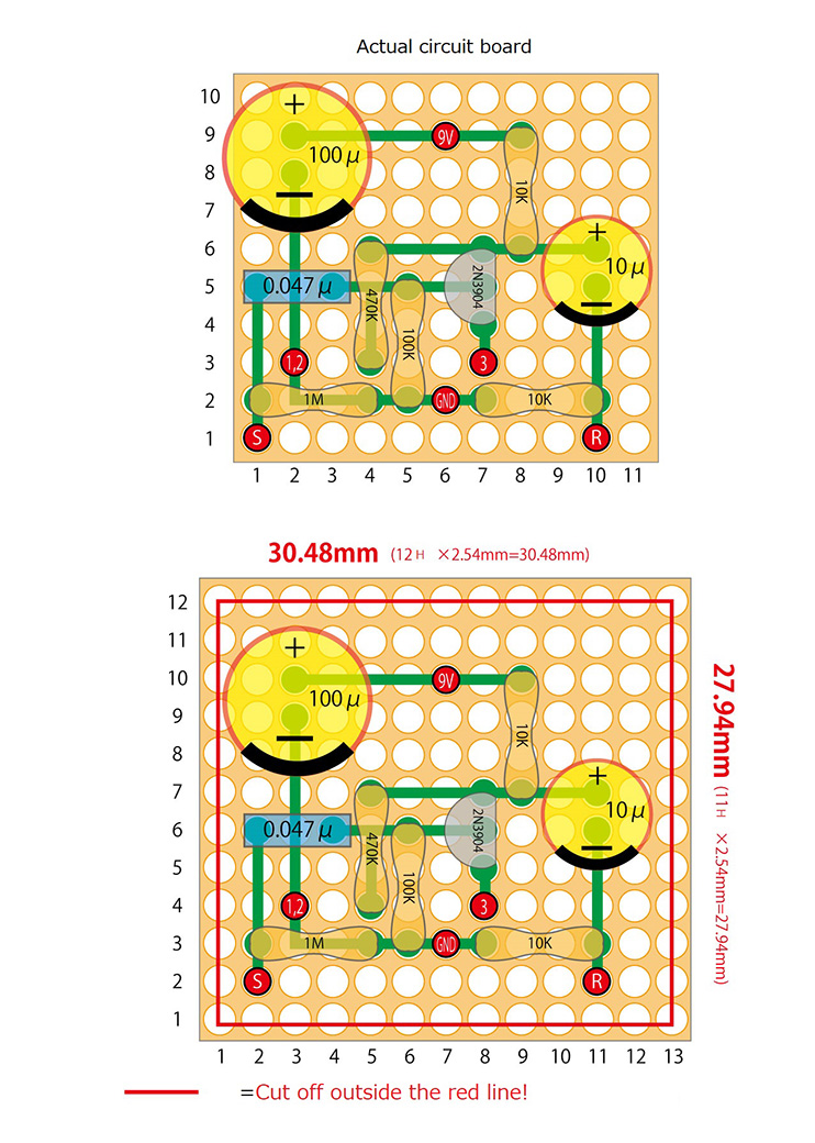
Also, I will show you circuit figure. This time, we will use Universal prototyping borad
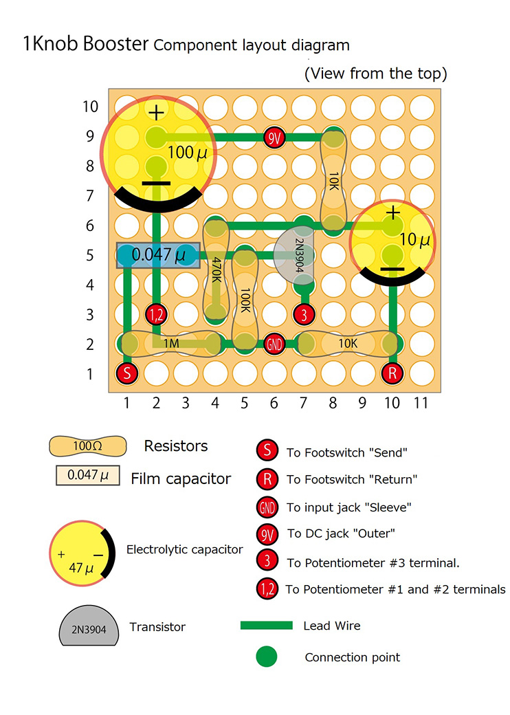
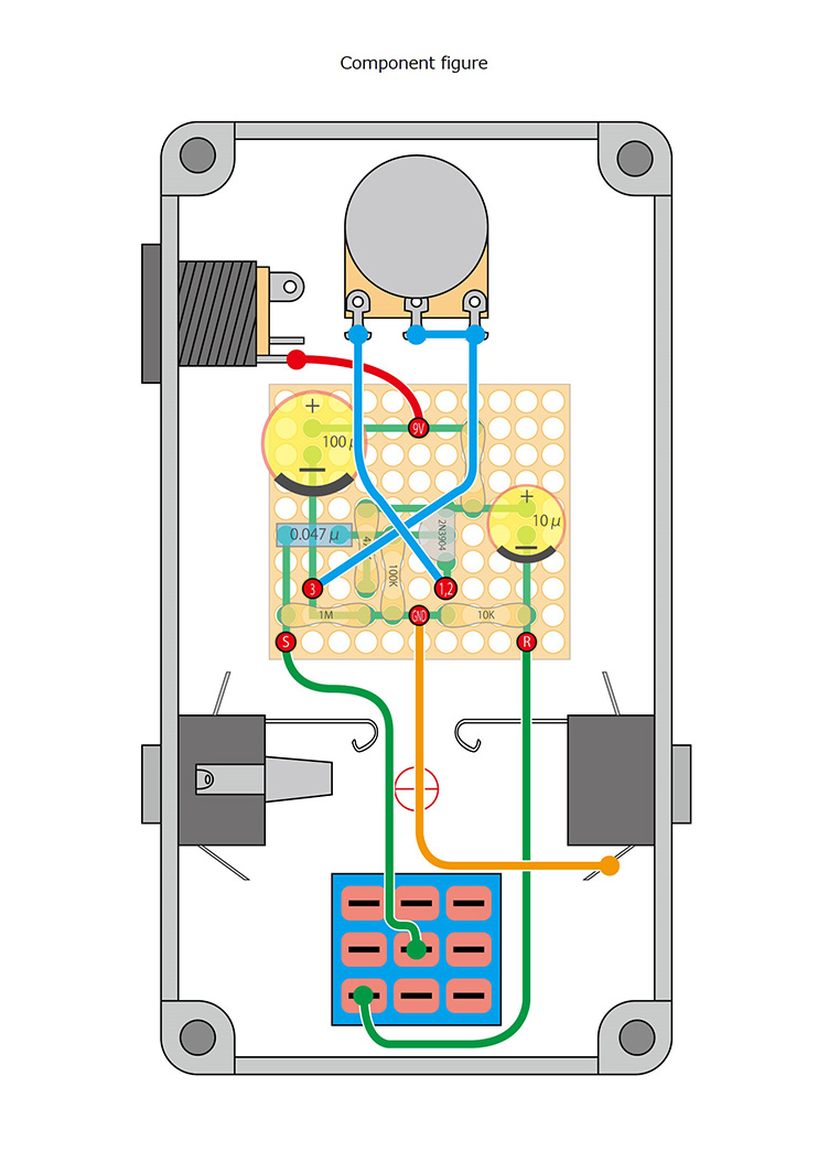
Please check these circuits and Actual layout figure.This time, I don’t teach you how to connect each parts and circuit board. I would like to you feel how big is your circuit and how to locate these parts in your chassis.
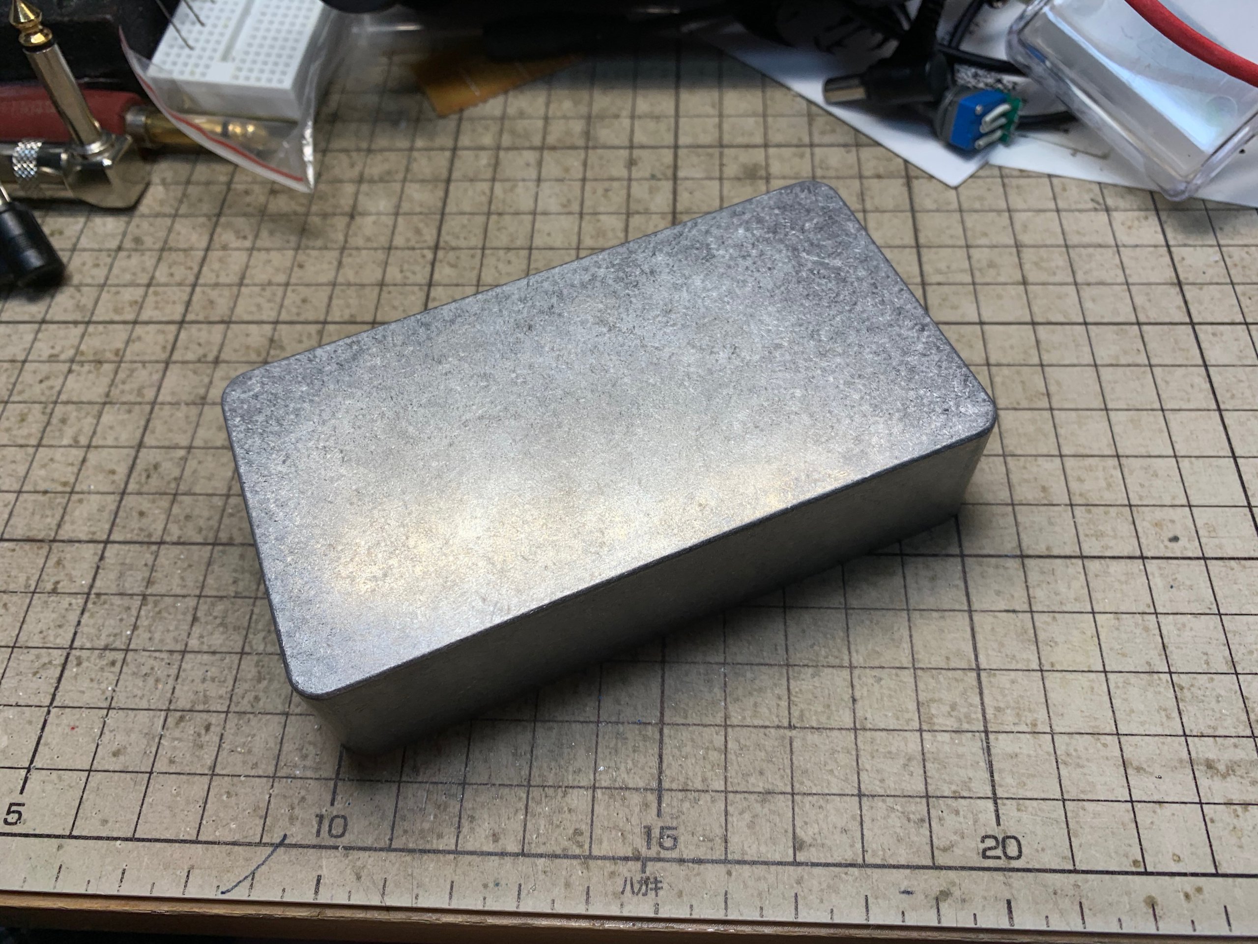
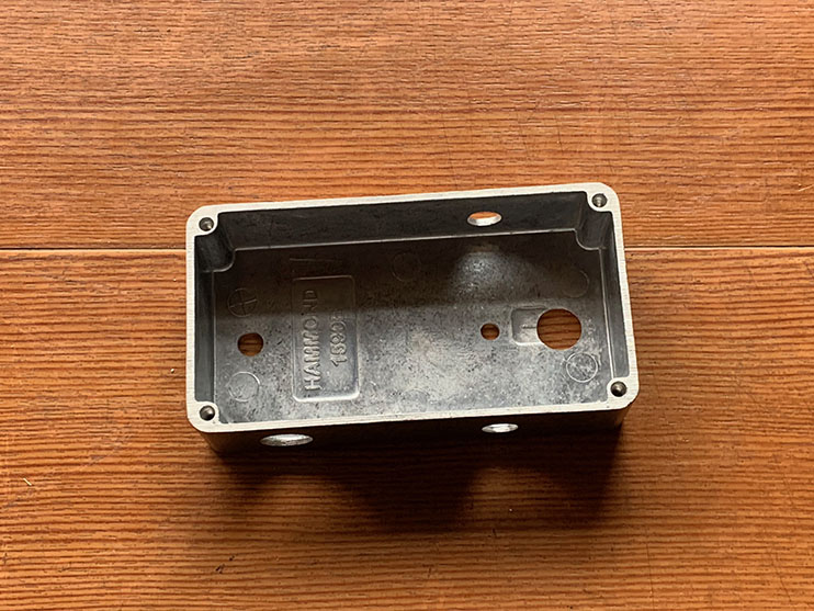
The square with many white circles is the universal prototyping board on the circuit diagram. 10×11 holes, it is not big board. That is why, we don’t need such a big chassis. We will use Hammond 1590B chassis. Also we will try to make a built in battery chassis.
Takachi TD6-11-3N chassi is available in this course.
Object: Booster with one Knob.
Circuit diagram, Actual layout figure available.
Chassis: Hammond 1590B
Battery available, True by-pass
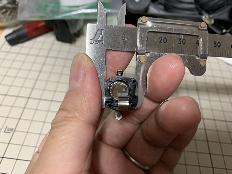
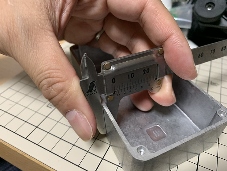
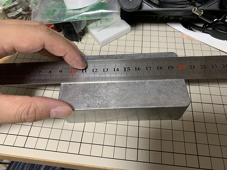
Measuring
Let’s measuring actual parts when you start building your effector. Also, you can check the data sheet from parts manufacturers.
Please make sure parts list.
Other manufacturers’ products can be used if they have the same specs and part number.
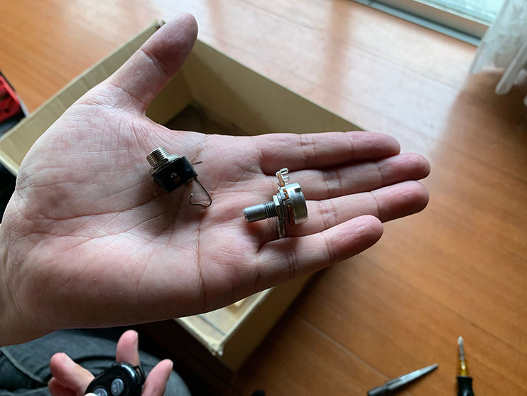
You do not need to measuring resistor or capacitor. These parts is on the circuit board. However,Please make sure to measuring these parts bellow.
・Footswitch
・Audio jack (Input and Output)
・DC power supply jack
・Potentiometer
You may found them, These parts are chassis and parts which direct mount on it. If you can understand these parts sizes, the chassis can be designed.
You can calculate how big is your this circuit board. Also, you need a extra 1 hole when you will make circuit board.
※ Each holes interval…2.54mm (1/10 inch)
Vertical…(10 holes+extra 1 hole)×2.54mm=
27.94㎜ (1 and 1/10 inch)
Horizontal…(11 holes+extra 1 hole)×2.54mm=
30.48㎜ (1 and 1/5inch)
Approximately 28mm×30mm
Parts location
When you made sure your parts sizes, Let’s try to Imagine where your parts be putted on chassis and determine your desired location.
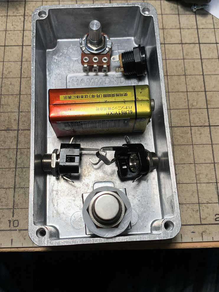
You may understand easily parts location if you can put your parts inside chassis.
I recommend to put a footswitch and potentiometer as possible as far. Because you will touch the knob when you will stomp the pedal if these parts are close.
If you have finished measuring and determined your parts location, Let’s draw paper template as your chassis design sheet. Also, this paper template be used when we are punching drill a hole location.
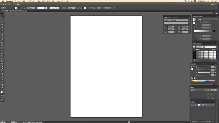
You can draw your chassis design by paper and pen but I recommend to use computers and appropriate applications. You don’ t need to care which drawing apprication is the best. I insist that your choice is the best!
However, Please be careful one big thing. Choose an application that you can edit by actual size. Some application is edited by points or pixels, but it is not actual size, just only display size. Sometimes it will be causes of a difference of the product size.
I will give you the lectuer with Adobe IllustratorCS6. . Copy free this lectures’ drawing data, you can use it freely.
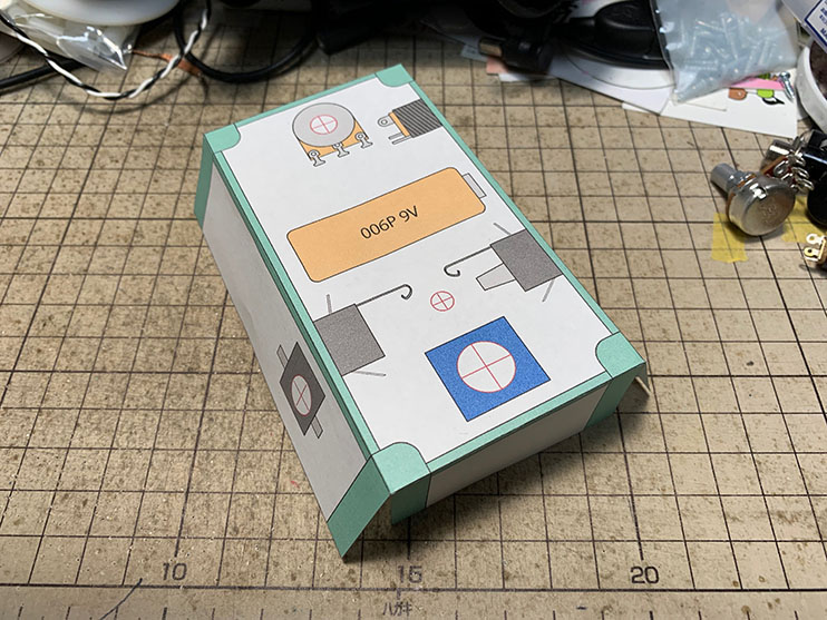
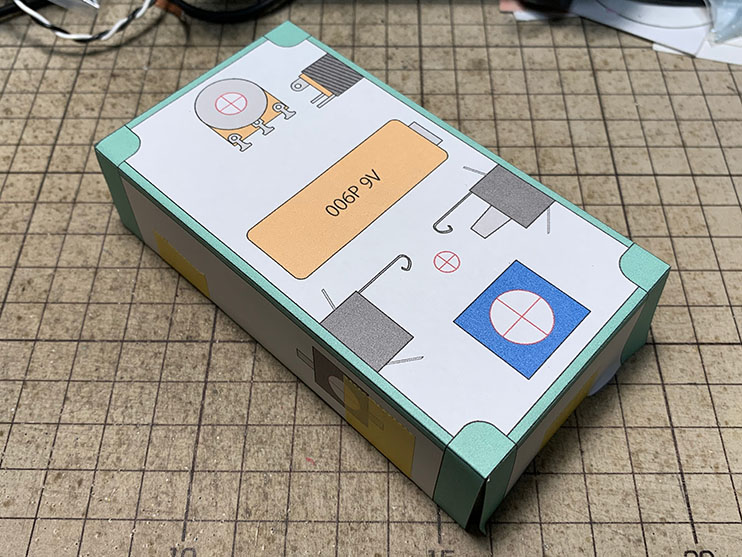
Development view first.
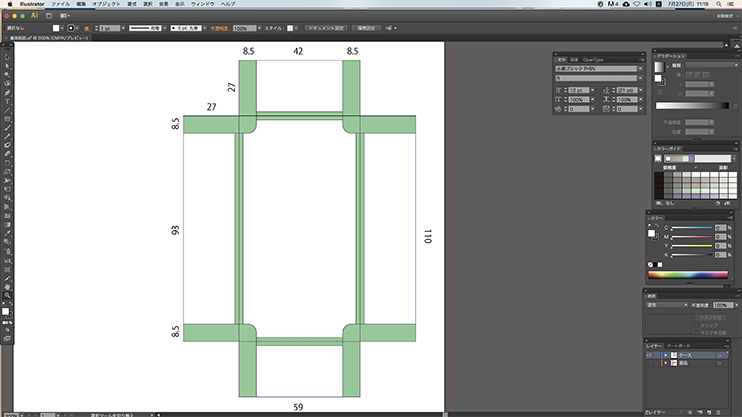
Make your development view from top of the chassis. Because Hammond 1590B has different sizes between top and bottom side. If you will draw in bottom size, your drawing will be biggar than actual size.
The chassis has a thickness of 2 mm. Also, screw holes too. You have to put a guide (margin for thickness and screw holes) on your drawing.
Draw the parts in the development view.
You have putted your actual parts in your chassis before you drawing. Let’s put your parts on your development view looking at them. Led cross marks are location for drill a hole. Do not forger them!
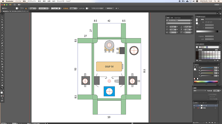
Arrange the parts location so that they do not interfere with the screw holes and thickness of the chassies.
Drawing is 2D, but actual chassis and parts are 3D. be careful interfere between parts and parts, or parts and chassis.
It looks great when the center lines of the parts are aligned.
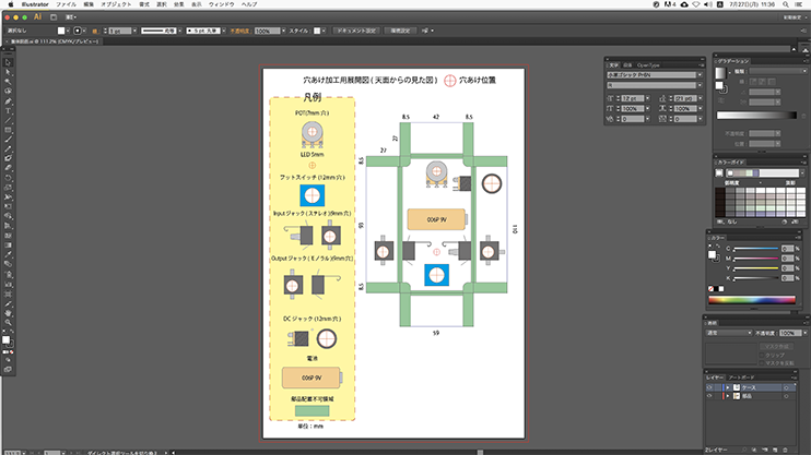
Copy free drawing data. Use the freely! You can choose your best data.
[wpdm_package id=’146986′] [wpdm_package id=’146987′] [wpdm_package id=’146988′] [wpdm_package id=’146989′]2: Making punch
Watch video first, for your understanding…
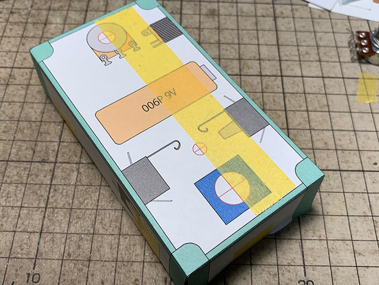
Print out your template. DO NOT Shrink and enlarge your data when you print out them.
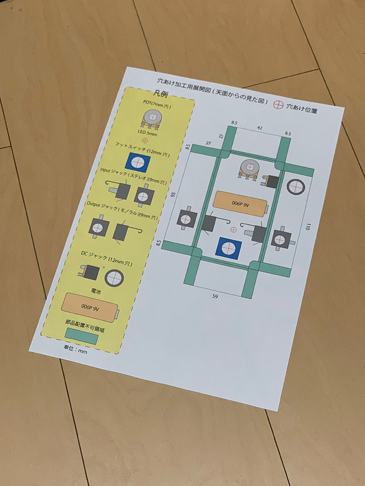
Cut the blank of the paper.
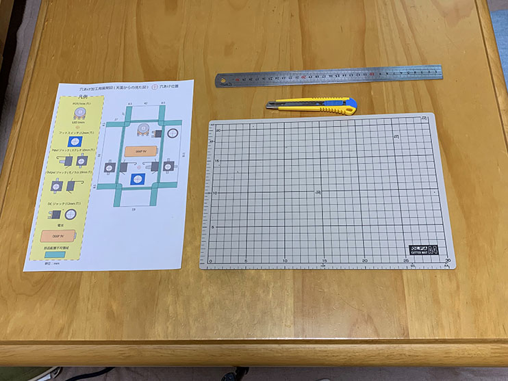
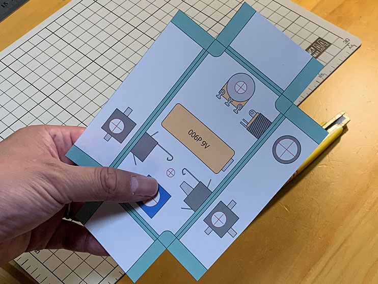
Put your template on your chassis and fix it masking tapes.
Put your parts on your development view and chassis.
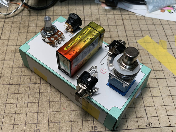
Please make sure, No interference each parts.
I would like to show you 1 good tips!
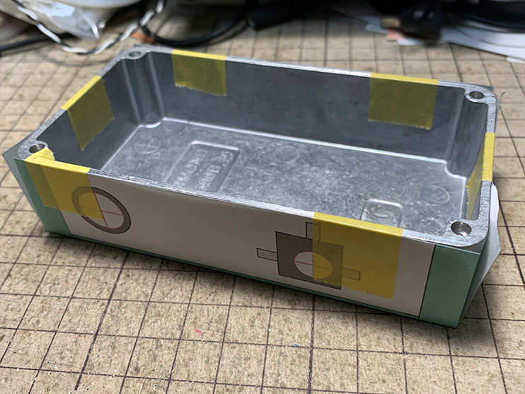
Put masking tape on your template where each drill holes center. This masking tape will be your exact ruler to align and drill holes. also you have to do samethings on another surface that need a drill hole.
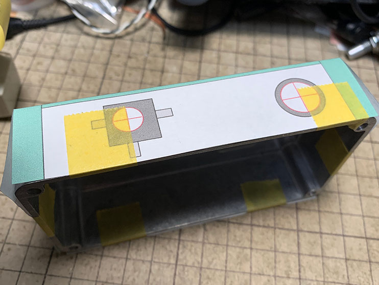
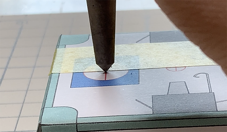
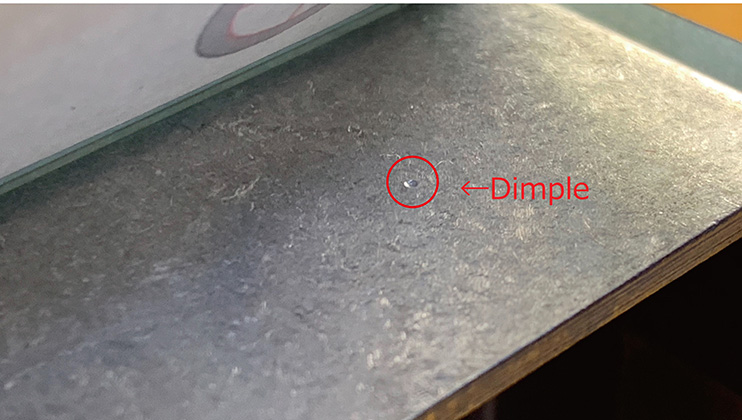
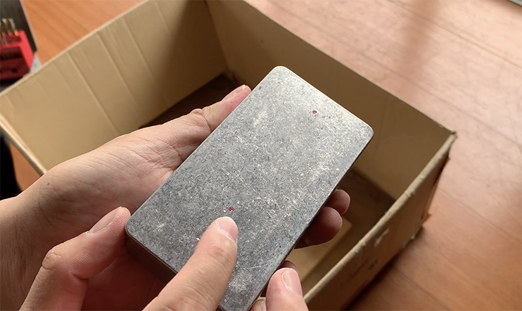
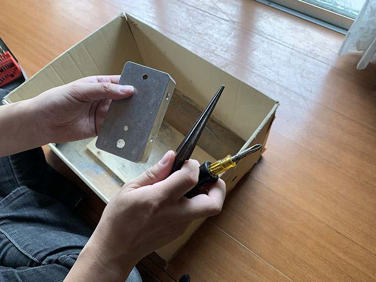
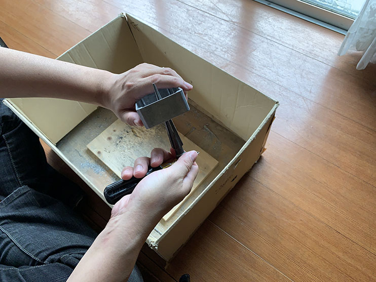
If you want to drill a hole on your chassis, you have to use power drill for them. But you can not use it with out guide. Drill tip will slip away from the hole location. That is why, You have to making a small dimple on your chassis before you drill a hole. This dimple will be the hook for your drill tip.
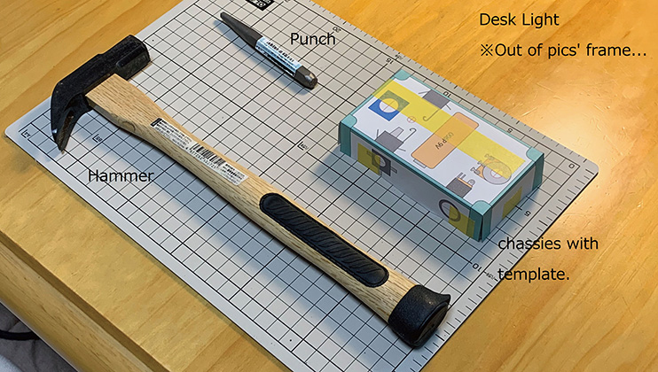
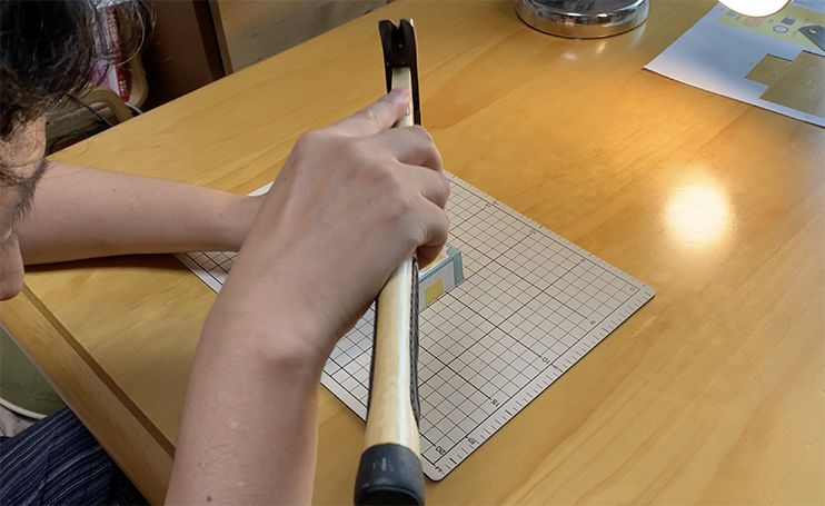
Punch and hammer. You don’t need to hit strong a punch on your chassis. Just tap it them.
Put your chassis on your work bench at Horizontal direction of masking tape.Masking tape direction is parallel on your body. Put your punchs’ tip on edge of masking tape. Dimple will be putted on the straight line and you never lost your exact locations of drill hole.
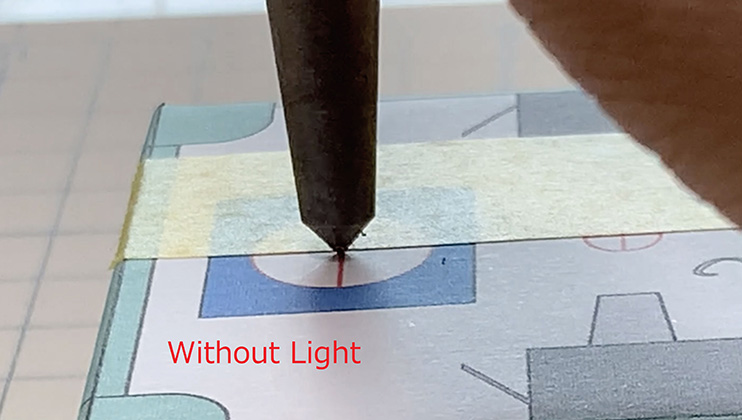
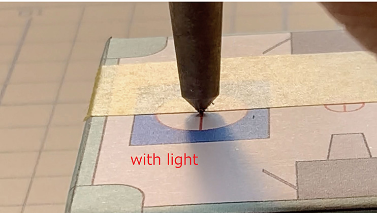
However, You can’t keep a exact locations of the holes of vertical direction on this way. I will use the desk-light for them.
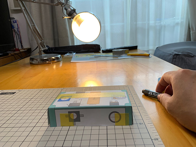
Put your desk-light against you, and keep low angle.
Put your punch. you can see the defference of the right location and your punch.
Let’s make all dimples for drill holes.
Remove all template from your chassis when you get all dimples. Please make sure all dimples are good for drill tip. However if the dimples are still shallow, or not steady, you have to punch again.
3: Drilling a hole
Watch video first, for your understanding…
start drill a hole.
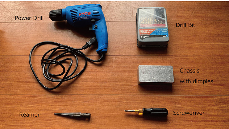
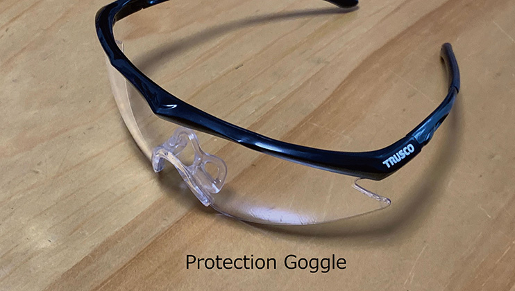
Also, You have to make sure and attention your clothes. DO NOT WEARING ANY GLOVES When you are useing power drill. Also, DO NOT WEARING LOOSEN CLOTHING. If you have a long hair, TIED UP BEFORE USE THE DRILL.
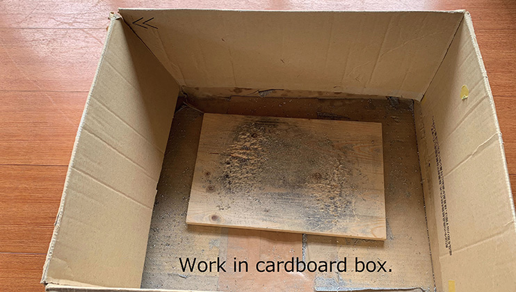
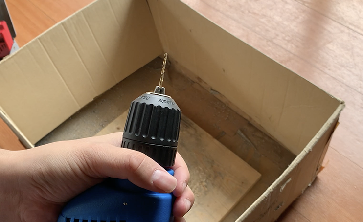
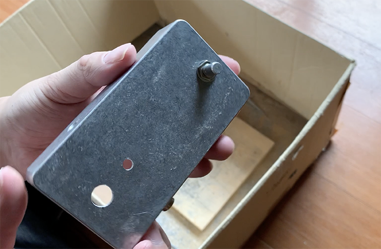
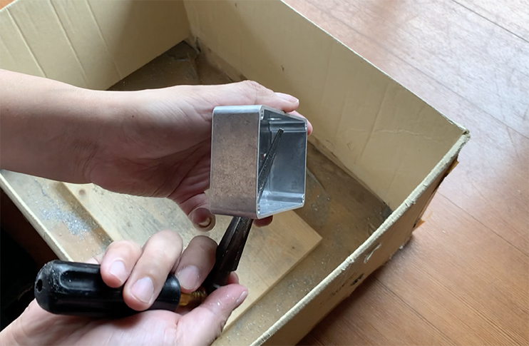
Also, I recommend to drill hole inside cardboard box. you can avoid spreading pieces of the metal and you can save your time for cleaning.
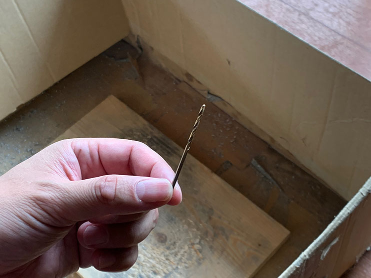
Drill bit is must be for the metal processing. but you don’t need to buy expensive one. I bought reasonable drill bit set. 1~10mm diameters sets of drill bit, almost 3000 JPY.
Drilling a hole
If you want to drill a hole, do not use your desired size drill tip first. You will not only lost your exact hole location but also sometimes you will fail a drilling. You have to drill a small size hole first, and expand the size of the hole little by little.
In the beginning, make a guide hole. I always use 1.5mm~2mm tiny drill for them.
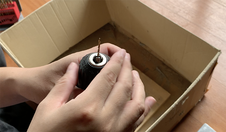
Make sure dimple location and put your drill tip on it.
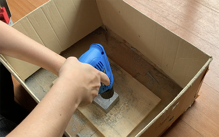
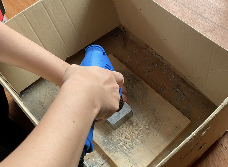
Hold tight your drill and start to drilling hole on your chassis. Keep vertical when you put your drill tip on your chassis.
You don’t have to press the drill hard against the chassis. It is okay to hold the drill so that it does not slip when it rotates. The weight of the drill itself and the force to hold it so that it does not slip and the rotation of the drill will open the hole sufficiently.
Please make all guide holes.

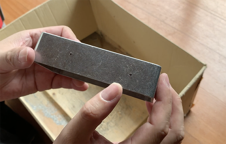
If you made all guide holes, Expand your holes.
Use a drill 1mm larger than guide hole to expand the hole. If you use a drill 1mm larger than the current hole, you can make to expand the hole cleanly.
If you are in a hurry and try to make the hole bigger all at once, the position of the hole will srip and you will fail to drilling. so don’t be in a hurry and work one step at a time.
Make it as big as you want.
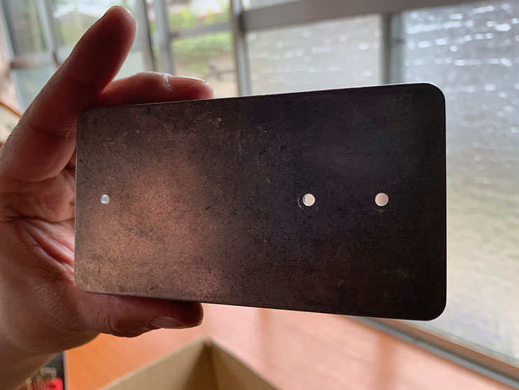
Please make sure the holes required size for the parts to be installed.
Pottentiometer.:7mm
Input and Output jack:9mm
Footswitch:12mm
DC power supply jack:12.5mm
Make sure you can install all parts when you have expanded each hole.
Do not make a hole that is too big for the parts. You can fix it by Epoxy patties, but it is so hard to beginners. I don’t recommend it.
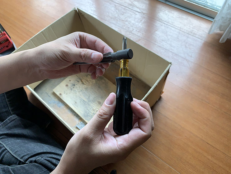
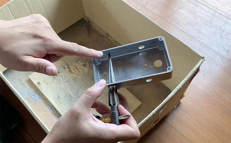
Expand further a hole with reamers.
The drill bits we prepared for this project are only available up to 10mm in size. The 12mm and 12.5mm holes needed for the foot switch and DC jack cannot be drilled with the drill bit alone.
So we use a tool called a reamer to extend the 10 mm hole to the desired size.
Put a bar in the hole in side of the reamer. It will be handle of reamer.
Grip the reamer tight. put and rotate a reamer on your holes that you want to expand.
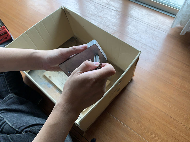
Put your parts and make sure hole size.
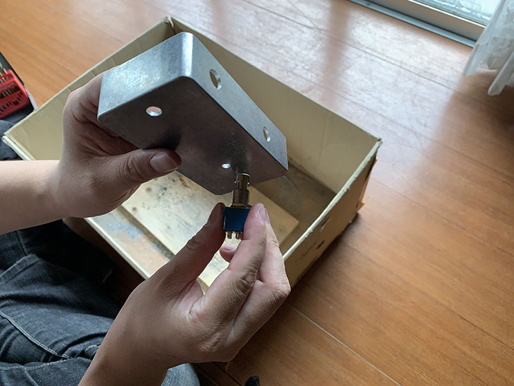
If you make the hole too big, you won’t be able to redo it, so check the size of the hole a little bit over and over again.
Fit tight, That’s right!
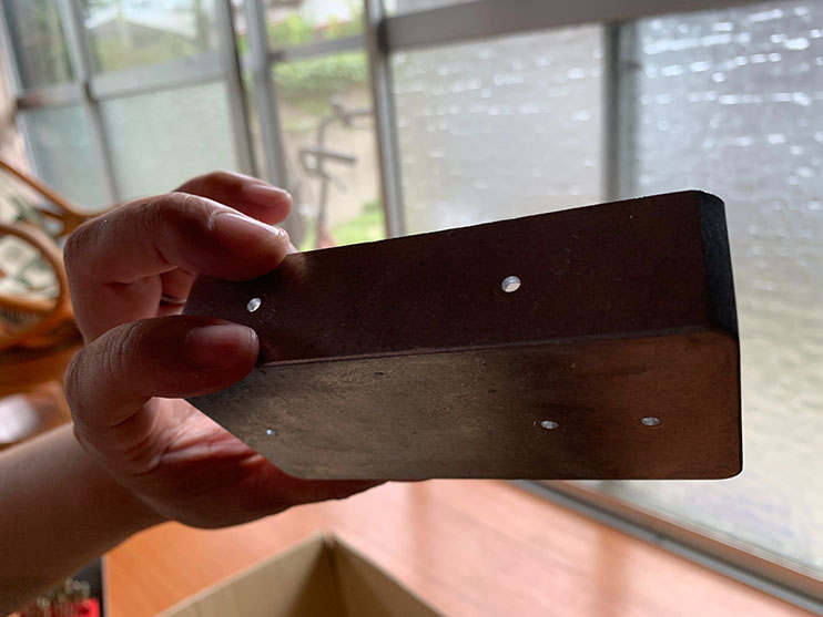
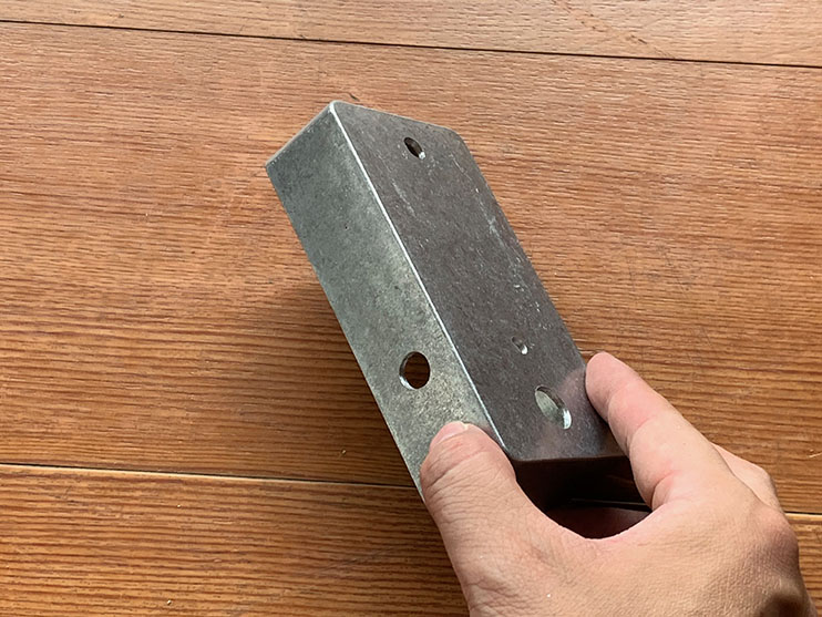
A place you can not use reamer.
The 12mm hole for the footswitch can be drilled with a reamer without problem.
However, the 12.5mm holes for the DC jacks on the side of the unit cannot be expanded to the desired size because the tip of the reamer hits the other side of the unit. How do I make it?
In that case, you can insert the reamer into the hole at a slight angle.
However, you keep slight angle from one direction, hole will be oval. You have to change the angle and direction again and again, make a exact sized hole.
DONE!!!!!
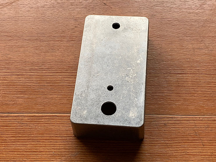
If you can find a cutting scaraps, please remove them the metal files.
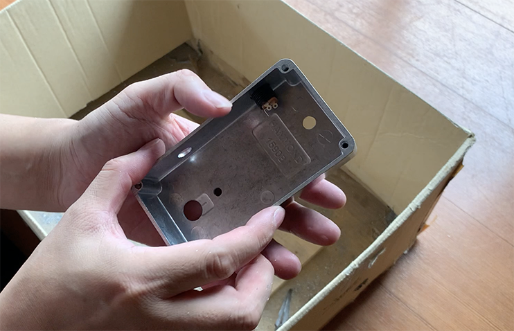
Check them all !
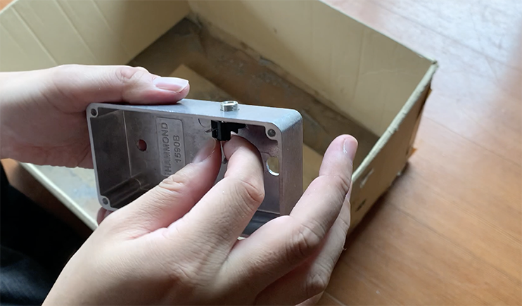
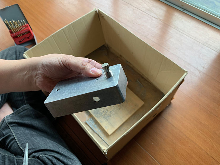
If you have made all holes, try to fit your parts on your chassis.
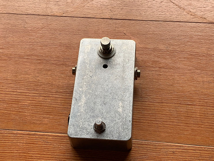
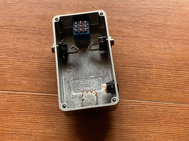
If you can put all parts tight fit, your job is done!
We are not responsible for any accident, injury or damage during your work. This article is not a guarantee of your safety.