If you want to build your effectors from scratch, You may have a lot of questions and wants to know the tips of them.
We are pleased to announce to launch The ECB Effector Building Course for beginners.The instructor is Hiroshi Ozawa, Sound Project “SIVA”‘s founder. He is also JPBA’s initiator.
This web course would like to introduce not only “How to build it” but also Hiroshi’s recommended tools, parts, etc…
We are providing to the contents that useful for not only effector enthusiasts but also who want to be a professional effect builder.
▼Instructor
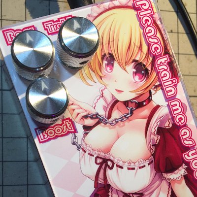 | Hiroshi Ozawa. Sound Project “SIVA”’s founder, effect designer and builder. “Siva” is the japan’s most famous “ITA effector” brand. “ITA” means “painful” literally, but it is an “OTAKU” slang in Japan, not a negative meaning. Almost pedal cover designs are seeking to be functional or cool. However, Siva is going a different way. Siva believes good effector needs a good cover design.He says “If it’s a cute girl? Your motivation will be higher.” » Sound Project “SIVA” |
Part1 “Tools”
Part2 “Parts and components-1”
Part3 “Parts and components-2”
Part4 “Case (chassis) processing”
Part5 “Painting or coating and finishing”
Part6 “Building an electric circuit board”
Part7 “Assembly”
Part8 “Work example”
Part9 “PCB electric board processing(KiCAD)”
※Subject may change without notice.
Obviously, You need to many kind of, and a lot of parts for your effector building. Resistor, Switch, Circuit board, and Chassis, etc…
I would like to introduce the Parts which we use for effect building. Also ,I would like to introduce how does it work. However, If we will try to full description, I need to write thick book like a dictionary. This article is just a summary, Minimum Knowledge of effector building.
I think you may build your effector without knowledge even If you never take a mistaking locations and numbers of resistance or capacitors. But if you need a modify your effector, or need a repairing, You should better to know about them. I hope this article will be your assistance of effector building or repairing.
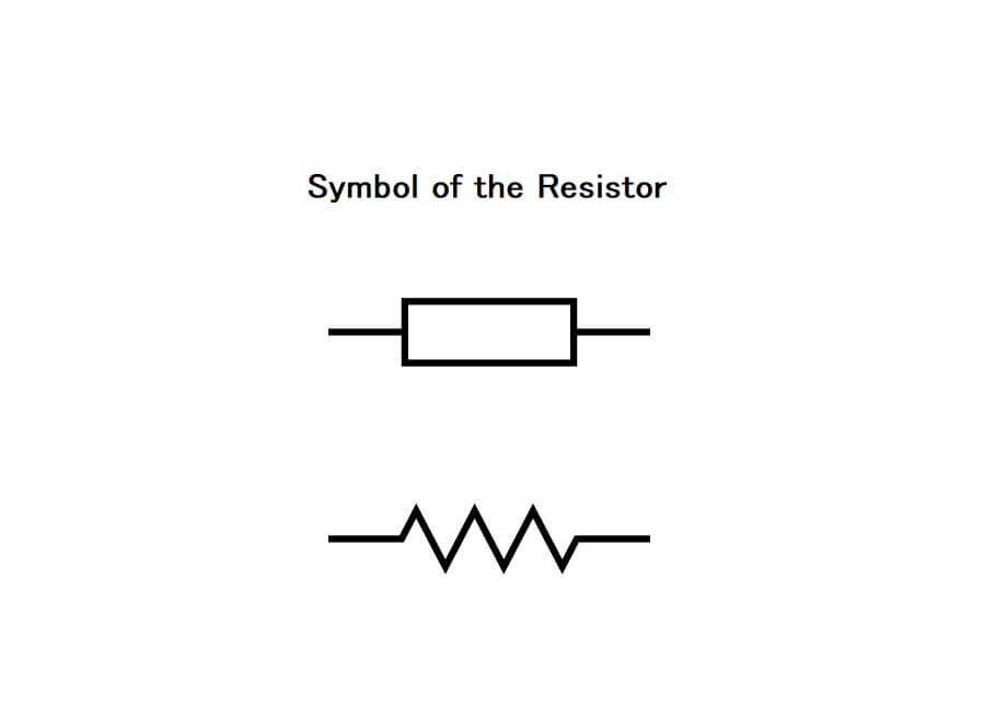
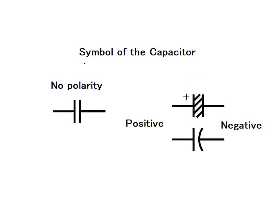
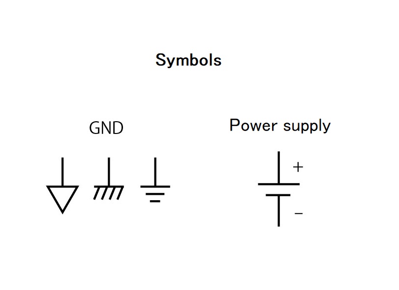
The circuit diagram is a guide of parts locations and numbers of resistors and capacitors. The circuit diagram has consisted of dedicated symbols. I also introduce dedicated symbols with each description.
I will separate this content two times because the effector is consists of many parts. We will introduce specialty tools and materials for drilling holes or finishing in another article.
1: Resistors
Resistors are parts that interfere with current flow. Resistors control current and voltage before transistor and Operational amplifier or tone control with capacitors. The resistor is an essential part of the effector.
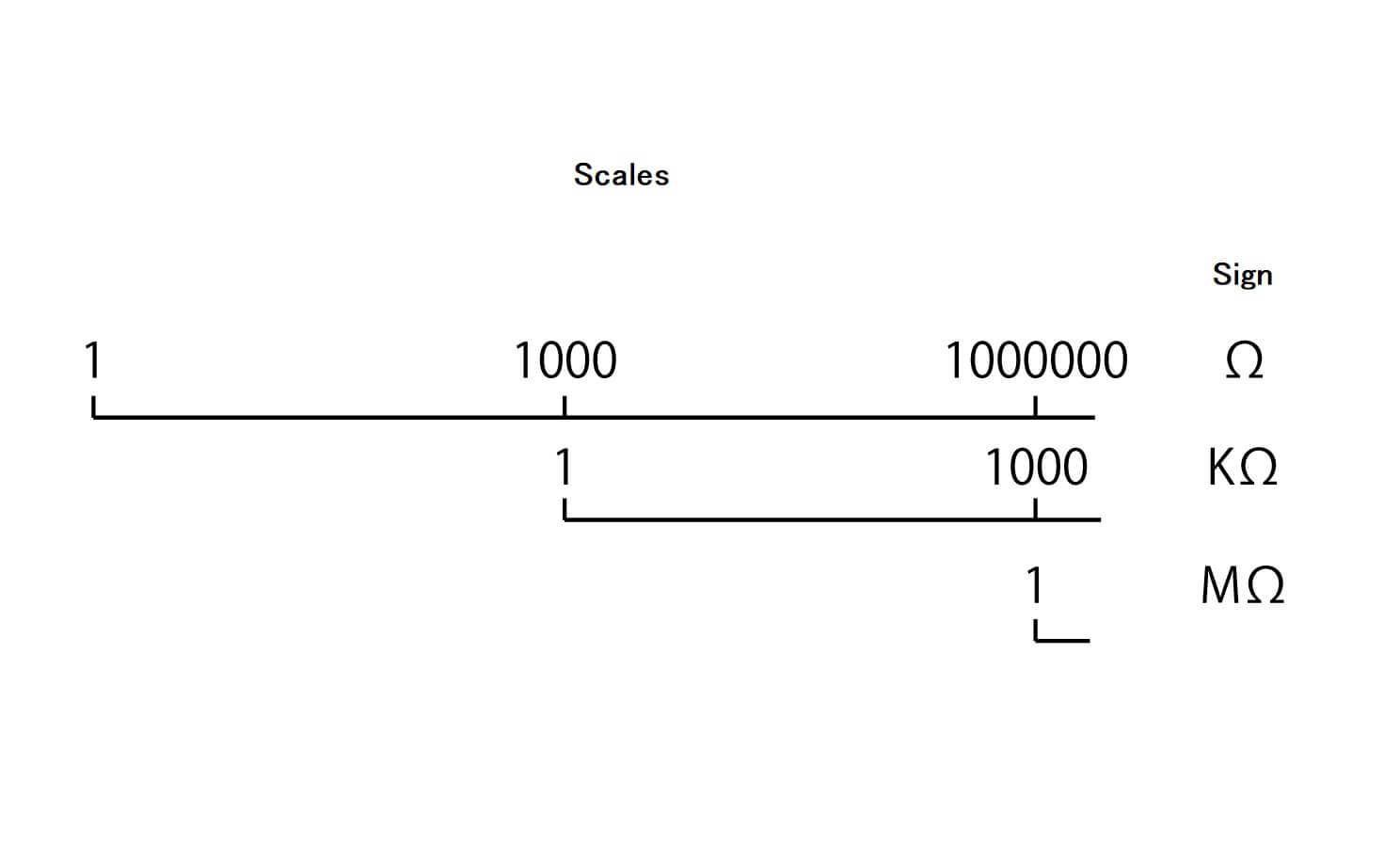
Resistance value
The symbol for the resistance value is Ω. Check the scales…
W (watt) means how much power resistor can withstand. 1/4W one is small and easy to handle for effector building. Using 1/4W resistor in this article.
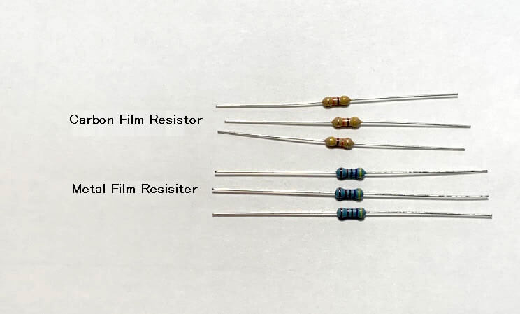
Types of resistors
You can find many types of resistor. “Carbon film resistor” and “Metal film resistor” are Appropriate for effector building. affordable price and compact. I would prefer to use “Carbon film resistor” in this article.
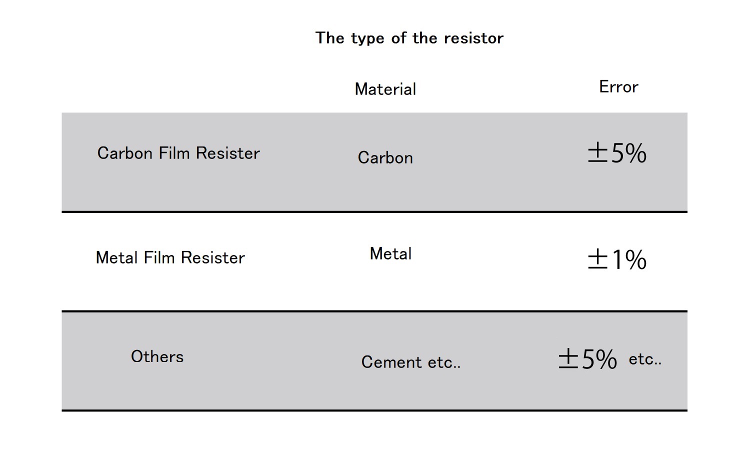
About the error (diffence) of resistance value
If you measure the resistance value with a tester, you can see that there are difference in the values even the same value resistor.
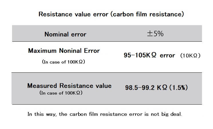
The carbon film resistor is also nominally an error (difference) in resistance value of ±5%, but it is quite rare such a large error. There is an impression that 5% is a large error, but in the case of an analog effector building, this error is not big deal.
First of all, I will considring using theoretical values.
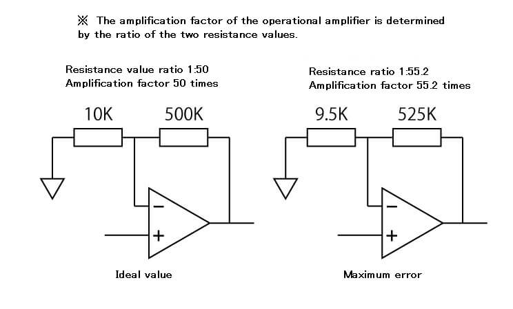
Two resistors are used to determine the amplification factor of the operational amplifier. The amplification factor is determined by the ratio of the resistance values of the resistors.
For example, to set the amplification factor of 50 times, set the resistance value of one to 10KΩ and the resistance value of the other to 500KΩ. Since the ratio is 1:50, the amplification rate is theoretically 50 times.
Assuming each error is maximum. The 10KΩ side is 9.5KΩ and the 500KΩ side is 525KΩ. When this is calculated, the amplification factor is about 55.2 times.
If there is a difference of 5.2 times as expected, it may be affected depending on the location of the circuit.
Then, does it actually hit an individual with such a large error? It’s a simple test, but I’m going to open a new 100-resistor resistor, take out 10 randomly, and measure it.
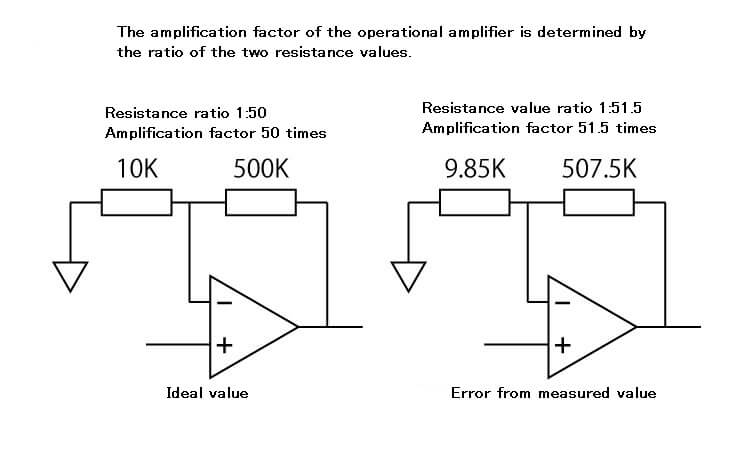
n this measurement, the lowest resistance value was 98.5KΩ and the highest resistance value was 99.2KΩ. The difference between individuals fits within the range of 0.7 KΩ (700 Ω), which is 1.5% even considering the difference from 100 KΩ. It is a value close to the metal film resistance, which is said to have a small error.
Applying to the example of the operational amplifier described above, if you calculate with a 1.5% error, even if the error is maximum, the amplification factor can be suppressed to about 51.5. Since it is assumed that the error is the maximum, the error will actually be smaller.
In this way, the carbon film resistance error is not big deal.
Direction to connect.
Since the resistor has no polarity, you can connect it in either direction.
2: Capasitor
Capasitor has many fanction.
1.Store an electric charge.
2.Allow DC but not AC.
3.Low frequencies signals are hard to pass, high frequencies signals are easy to pass.
Also, there are more types than resistors, and capacitors are one of the biggest concerns about the selection. This article focuses on “Capacitance” and “Withstand voltage”
Capacitance
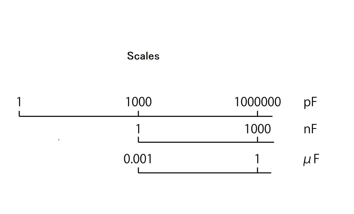
The symbol for the capacitance value is F (farad). Check the scales…Farad represents how much electricity can be stored.
Withstand voltage
The symbol for the capacitance value is V (Volt). Check the scales…V represents how many volts it can withstand. If much more voltage than withstand voltage, the capacitor will exploding. Be careful withstand voltage and your desired voltage.
Effectors always using 9v DC power supply ordinally. That is why you have to select over 16v withstand voltage capacitor. Then, If you design a circuit that boosts the power supply inside the effector, you must be careful about the withstand voltage of the capacitors.
Type of capacitor
The inside of the capacitor has a structure in which an insulator is sandwiched between two conductors connected to each lead wire. The type is different depending on what kind of material is used for the conductor. The types of capacitors are roughly divided into two groups. In addition, the types of materials differ depending on the material.
1: Capacitors without polarity (non fixed orientation)
The capacitors can be connected in any direction.
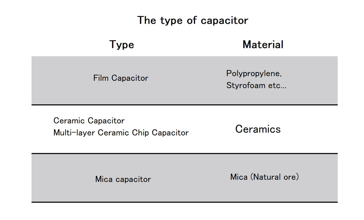
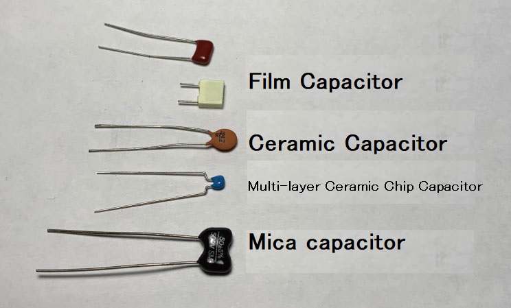
Film Capacitor
Made form Polypropylene or Styrofoam, petrochemical materials.
Using for audio circuit in effector mainly.
Ceramic Capacitor
Made from ceramic, old fashioned, brown, disk forme capacitors. You can see guitar tone control circuit.
Multi-layer Ceramic Chip Capacitor
It is a one kind of ceramic capacitor with a structure in which many dielectrics are stacked. Multilayer ceramic capacitors, which are small in size and have many capacitance values, are very convenient for building effectors. Use it frequently in effector building and the following examples.
Mica capacitor
Made from Mica, Natural ore, precision and good at Characteristically audio. However cost performance is not good. more expensive than other capacitors.
2: Capacitors with polarity (fixed orientation)
The capacitors can be fixed direction.
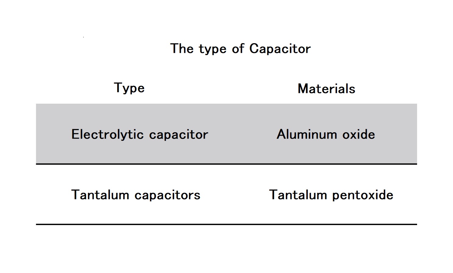
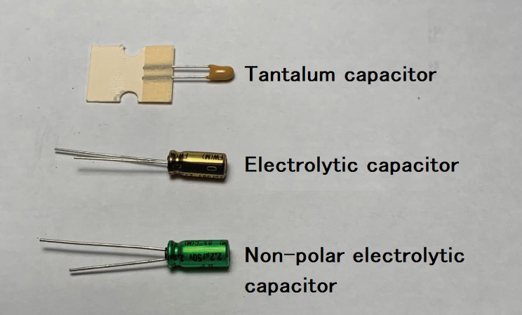
Electrolytic capacitor
2 metal plates built in the chassis. These 2 metal plates has chemically react on the surfaces to oxidize (rust). These rusts are insulator. The feature is that the capacitance is large from about 1 μF to 10,000 of μF. Electrolytic capacitors are the cylindrical parts that stand up inside many home appliances. There are also a non-polar type or not.
Tantalum capacitors
Made from rare-metal,Tantalum and good at Characteristically of audio and long life. But be careful for handling.
How does the capacitor’s work on the effector?
“Store electricity.”
Using Low Frequency Oscillator, building a Modulation effectors like tolemoro.
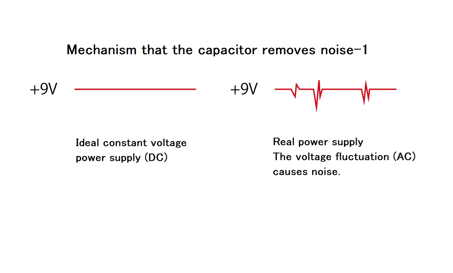
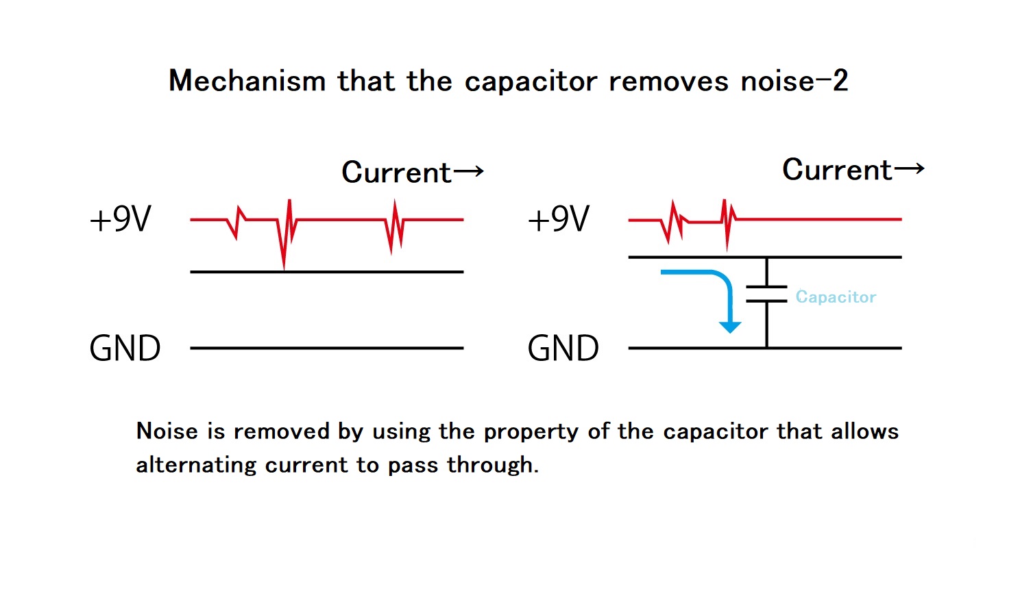
“Passing only AC not DC”
This function is appropriate for noise reduction.If your signal is not good, not clean DC current, it may couses noise.
However, You can not get a perfect DC current on your real circuit. Sometimes, AC signals will get on your circuit and make a noise.Therefore, using a capacitor, let the AC signal lead to Ground.
“Easy to pass low frequently signals, but Hard to pass high frequently signals…”
You can imagine easily, Tone control is the system that adopted this function. Using capacitor, and reducing treble tone.
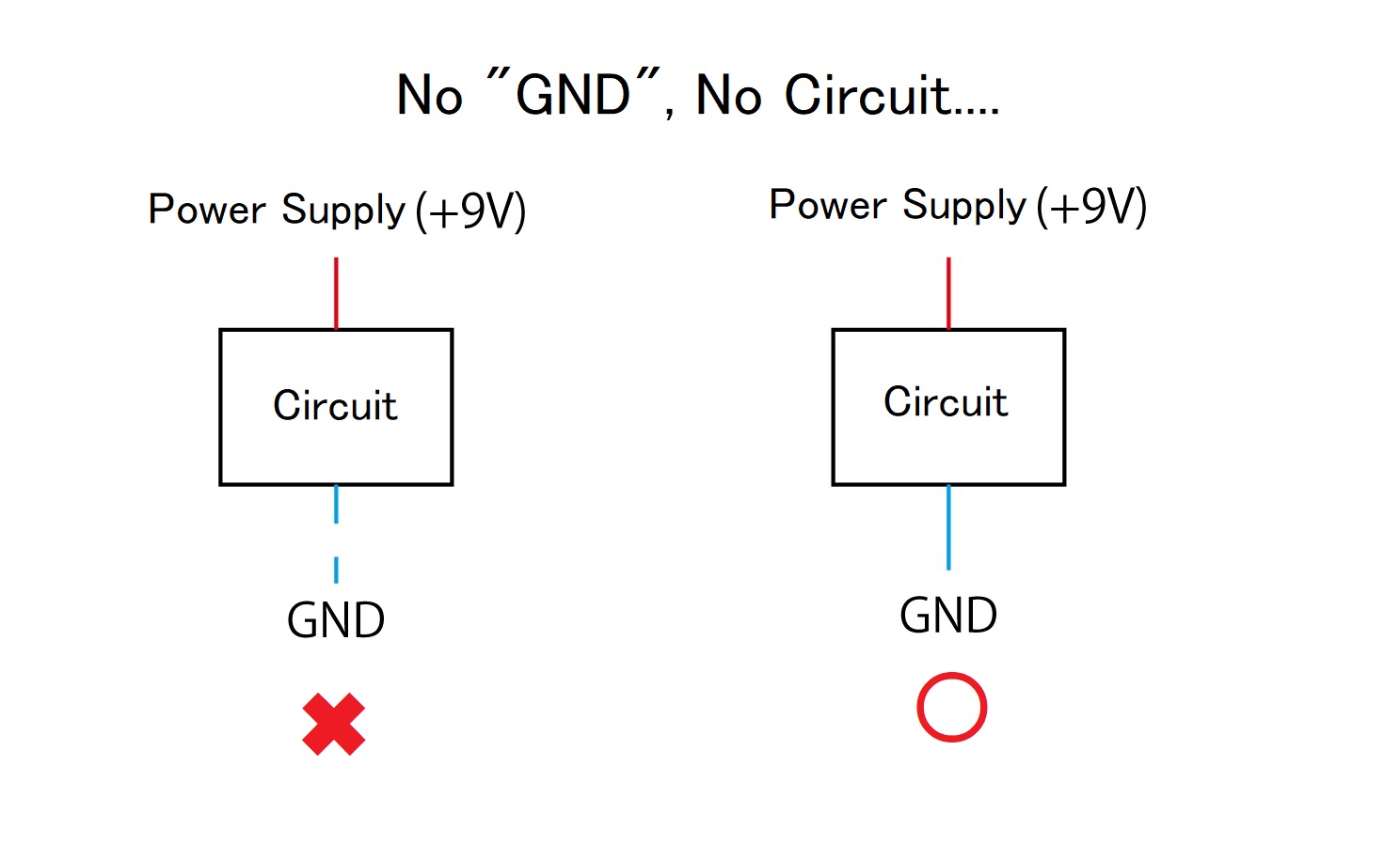
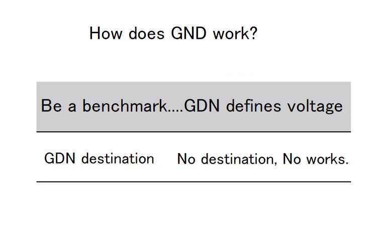
Column : What is the “GND” ?
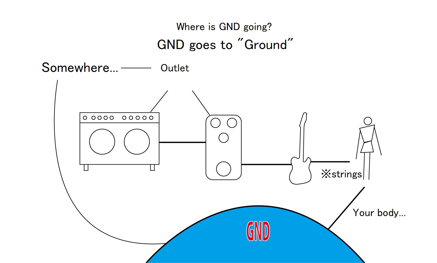
“GND” means “Ground”, also known as “Earth”.
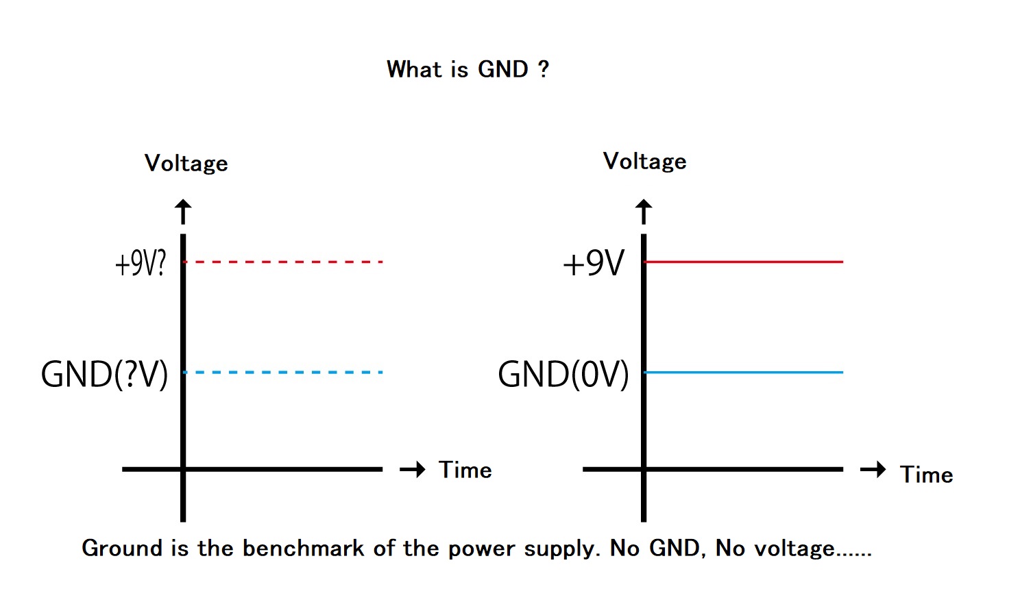
“GND” is not means “Planet Earth”, it means bench mark of the electric circuit. Effector is also electronic devices, therefore, need a benchmark. Electric bench mark in effector is 0 volt. if it there is no benchmark, 9v power supply is not exist on the circuit.
Then, where is the 0V=GND concretely? it is the guitar strings, effector’s aluminum case or output jack connected by the shield wire.
Please do not misunderstanding, battery’s negative is not 0V, ground. It just difference of the -9 voltage, not ground.
Electric power from 9v battery goes to transister or operation amp. Where these electric power goes to after working? It is “GND”. No direction electric power is no meaning, 9v power supply and Ground must be connected through some electric conpornents.
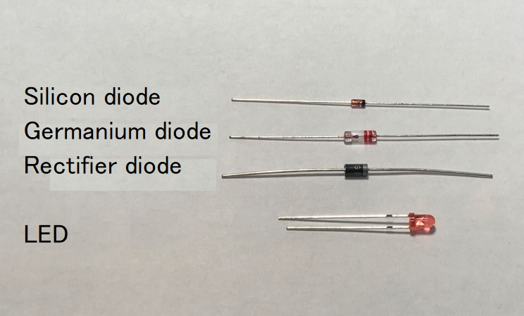
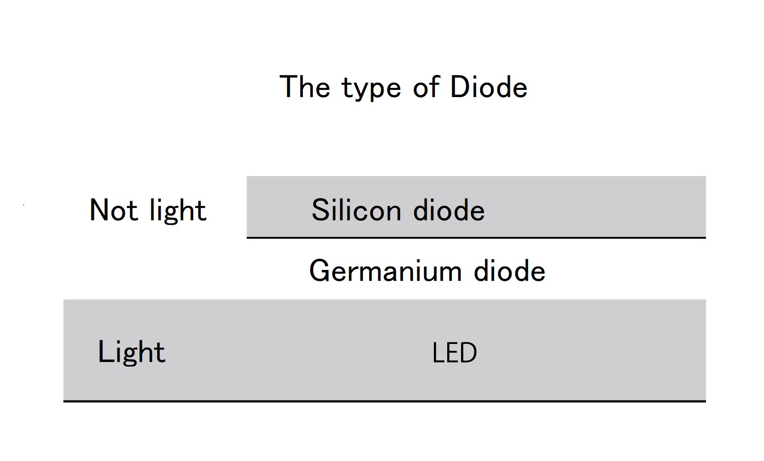
3: Diodes
Diodes and LEDs are semiconductors that work by passing electricity in only one, fixed direction. LEDs are one kind of diode, but they emit light when electricity is applied.
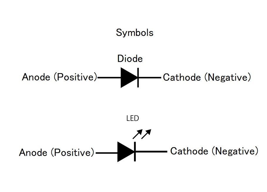
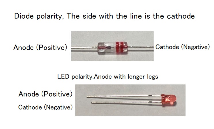
As a characteristic of diodes, electricity is unidirectionally applied only when a certain voltage is applied. The diode has two electrodes, labeled as the anode (+) and the cathode (-). Electricity flows from the anode (+) to the cathode (-).
When you building your effector, a diode is used as a measure to prevent damage when the electrode of the power supply is located in reverse. Also, Diode is an essential part of building distortion pedals.
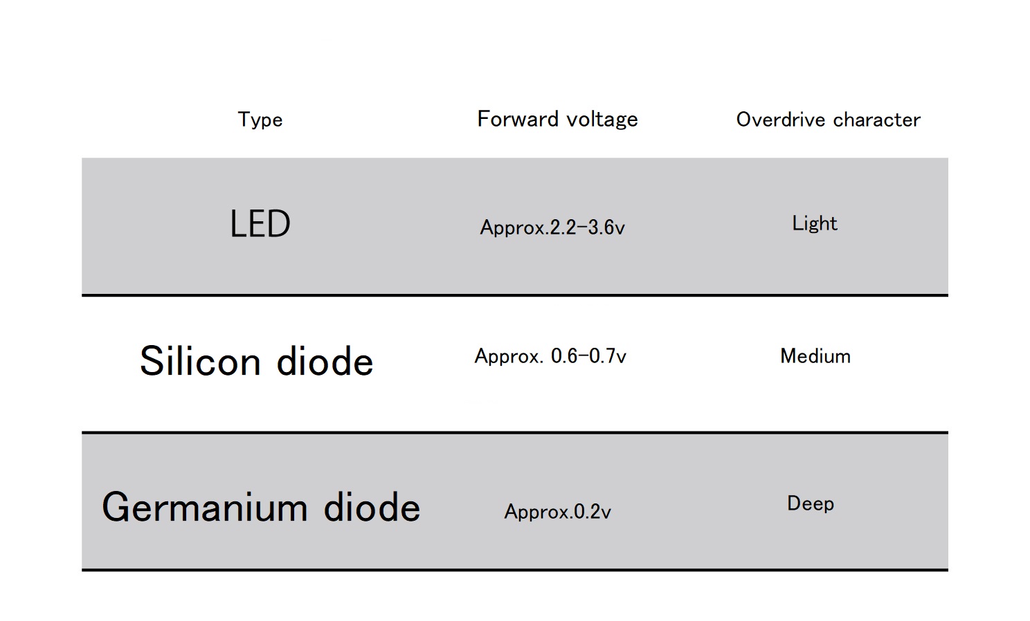
If you want to build distortion or overdrive pedals, These sounds depend on the type of diode. The sound character difference depended on the difference in the voltage (forward voltage) at which electricity flows when a certain voltage is applied, or the difference in the material of the diode (silicon, germanium). Generally, the lower the forward voltage, the deeper the distortion.
How LEDs are used
The LED is also used as an indicator for visualizing the effectors function On / Off. This is the way it should be used mainly for effectors.When using the LED for the purpose of emitting light, connect a resistor (protection resistor) to prevent excessive current flow. The protection resistance changes depending on the amount of current flowing. The LED becomes darker as the resistance value is larger (current amount is smaller), and the LED is brighter as the resistance value is smaller (current amount is larger).
Suitable resistance is calculated by specifications called the LED datasheet.Deciding how much current should flow below the maximum current. You can find easily a specialized calculator on the internet Thankfully.
These websites provide a calculation tool that calculates how much resistor to use when you input the power supply voltage and the amount of current you want to flow, so it is convenient to use it.
http://akizukidenshi.com/catalog/contents2/led-r-calc-pc.aspx
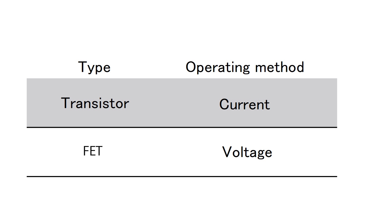
4: transistor and FET
Transistor and FET have 2 main roles. Amplifying signals and Switches. A transistor or FET can be the ”heart of the effector” even if it’s just only one. I will write it here briefly.
Transistor and FET are used to amplify the signal in effector mainly. Speak casually, what is different Transistor and FET ?”Work by the current is a transistor” and “Work by voltage is a FET”.
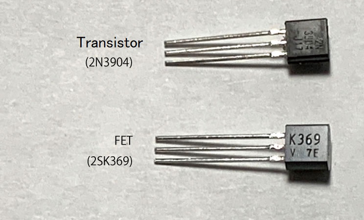
Current Transistor made from Silicon but used to made from germanium before. You cannot find a germanium transistor right now.
3 legs….
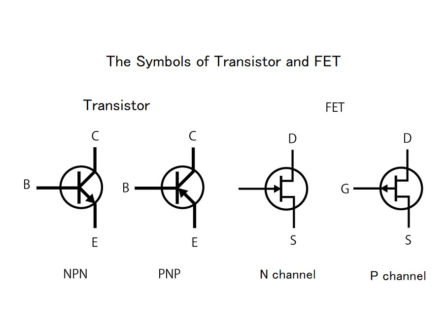
The transistor has three legs: emitter (E) collector (C) base (B). The order in which the legs arrange is sometimes different, please make sure and check the datasheet from the transistor manufactures. Transistor made from Silicon but used to made from germanium before. You cannot find a germanium transistor right now.
The amplification factor changes depending on the ratio of the resistance values of the resistors connected to the emitter (E) and collector (C).3 legs….
Like a transistor, a FET has three legs, which are named source (S) gate (G) drain (D). it’s recommended to check the datasheet from the transistor manufactures.
Each “type” in transistor and FET
Transistors and FETs can be categorised into two types roughly.
Transistors are categorised “NPN type” or “PNP type”.
categorised Depending on whether it is connected to the emitter or the collector on the circuit follows.
FET are also categrised “N channel type” and “P channel type”.In N-channel type, current flows from the “drain to the source”. The P-channel type current flows in the opposite direction and flows from the “source to the drain”.
5: IC (integrated circuit)
Operational amplifier
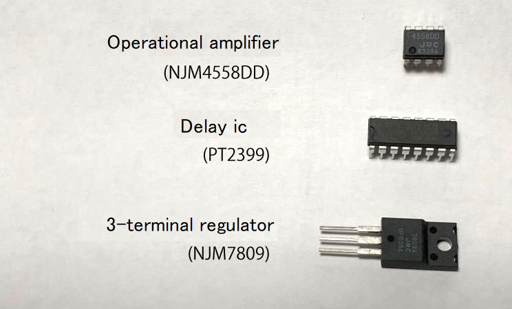
You can find various kinds of ICs in this world, but the operational amplifier is the most used IC for building effectors. An operational amplifier is a component in which many resistors, diodes, transistors, etc. Tightly packed in a small chassis, and it is a component that forms an amplifier circuit in a small space.
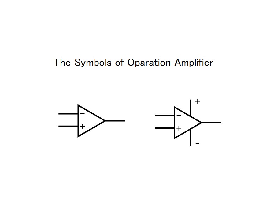
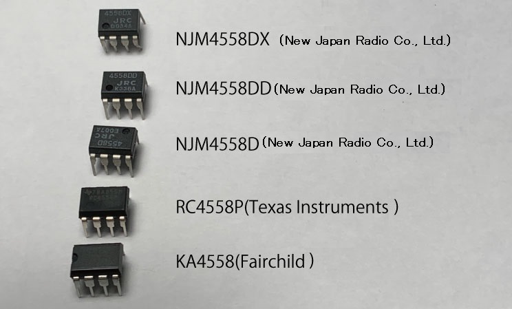
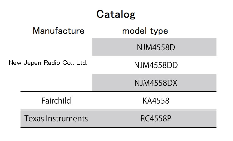
The operational amplifier has more than eight legs, and each has a different function. The operational amplifier has 1 or multiple circuits inside.An operational amplifier with two circuits is used to building effector commonly. Model number “4558” that is a typical two-circuit operational amplifier.
You can find a 4558 Operational amplifiers released by various manufacturers. There are slight differences depending on the manufacturer, but all are the same “4558”. and the basic structure is the same. Basically,Operational amplifiers with the same numbers have the same legs placement, so they can be replaced.
Besides Operational amplifiers, regulator ICs that produce a constant voltage are often used. A regulator with 3 terminals is really convenient because it requires few external parts and makes a clean power supply easily. There are various other types such as dedicated ICs for delay or reverb effects.
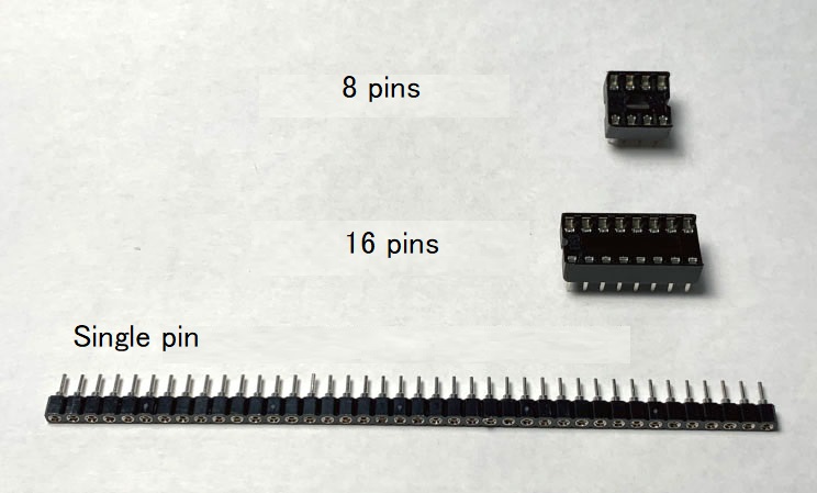
6: Socket
It is recommended to use sockets for semiconductors because it is sensitive to heat,direct soldering may causes of damage. sockets also provide easy replacement of parts, which is useful when you want to try various differences resistance values.
7: Circuit board.
A circuit boad is board for forming a circuit by placing and connecting parts such as resistors and ICs. There are two types of printed circuit boards: pre-wired printed circuit boards and universal printed circuit boards.
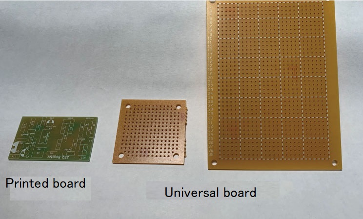
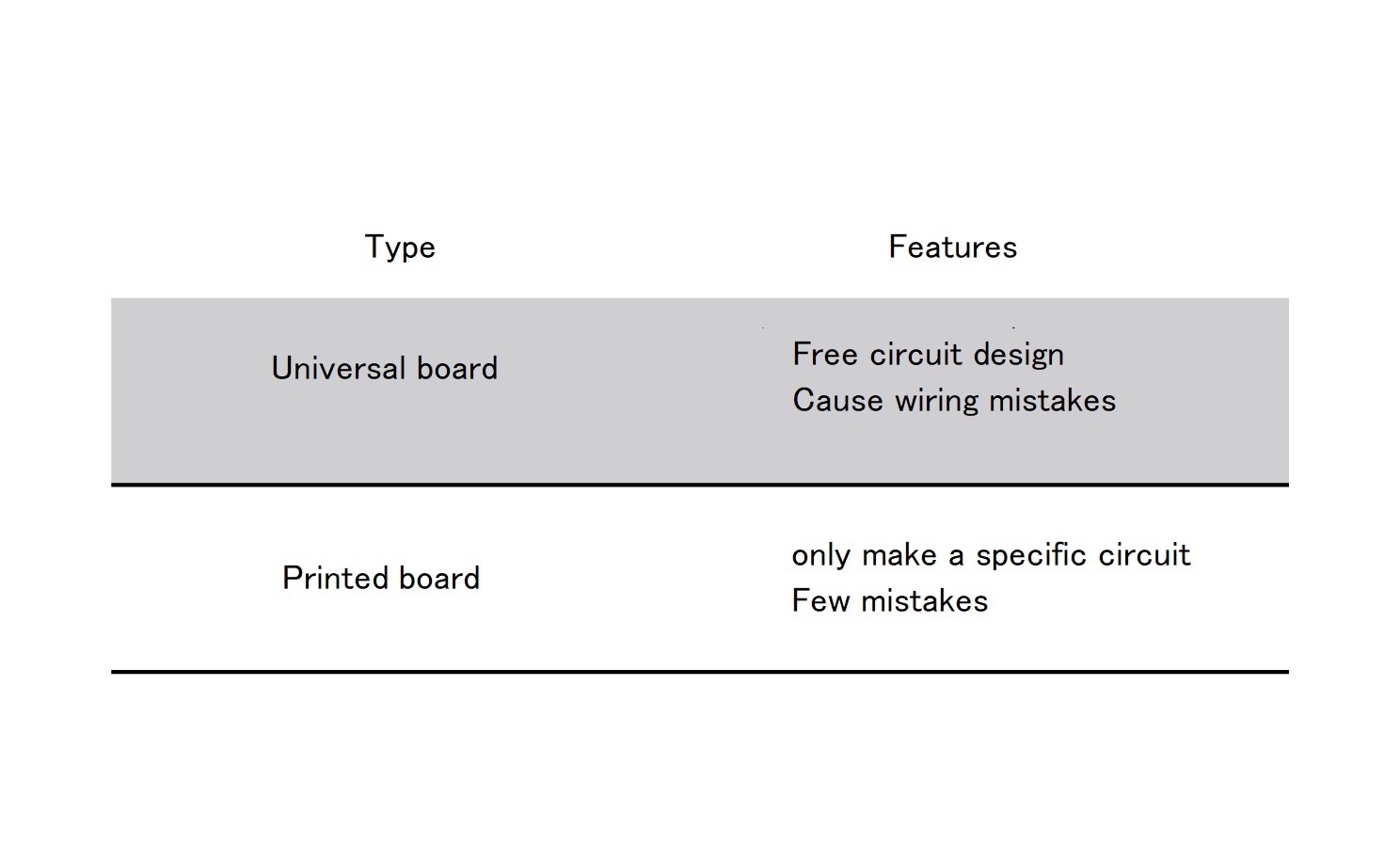
・What is a printed circuit board?
The printed circuit board is the board which wiring has been completed with copper foil. It is easy to build your circuite correctly.
However, it can only be used for certain purposes, you can not chenge the wirig diagram and design. It is easier and safer to use a printed circuit board when making a lot of the same effector or making a large circuit scale.
How to make your own printed circuit board.
② Transfer it to the copper-foiled surface of the printed circuit board.
③ Etching is performed to dissolve unnecessary copper foil.
④ Further, make a hole for attaching the parts.
Etching is a technique that uses the corrosive effect of sulfuric acid and the like to apply resist treatment (rust prevention) only to the necessary copper foil parts and dissolve only the unnecessary parts.
Sulfuric acid used in etching is a toxic substance. Work safity, wearing protective suit and gloves. When handling or disposing of the product, follow the procedure and method specified by each local government.
・What is a universal board?
The universal board is not pre-wired and designed, Connects the legs of the parts together by yourself. The Universal board is made from glass epoxy or paper phenol. Paper phenol board is better than glass epoxy because It is an affordable price and easy to cut to any size. In this article seriese, I will first introduce how to built it using a universal board.
If you try to make your own printed circuit board, you will spend a lot of time and money.Also,you have to prepare a corrosive liquid for etching and tools for pattern transfer, and to properly dispose of toxic waste liquid generated by etching.
Nowadays, there are some vendors who make PCBs cheaply, so I recommend you to ask the vendor if you want to make PCBs.
I will introduce later in this series, how to make data using a board design software called KICAD and order a printed board from a vendor.
We are not responsible for any accident, injury or damage during your work. This article is not a guarantee of your safety.